
Beam Shear, Moment and Deflection Diagram Calculator
Select a beam configuration, enter your parameters, and view the resulting shear and moment diagrams. Give it a moment of inertia and it plots the deflected shape as well.
Select Beam Type
Tool NotesWhat it does, the formula, and what it assumes
What this tool does
Draws the shear and moment diagrams for a single-span beam and gives you the numbers off them: reactions, maximum shear, maximum moment and where along the span each one lands.
Covers simply supported and cantilever spans under point loads, uniform loads, varying (triangular and trapezoidal) loads and combinations of them. The calculator primarily determines structural demand. Any steel-strength comparison is a preliminary check and is not a substitute for a complete AISC member design.
Given a moment of inertia, taken from the selected member or typed in directly, it also plots the deflected shape and reports the maximum deflection, where along the span it occurs, and the L/δ ratio.
Formula
Every case comes out of the same chain of relationships: shear is the integral of load, moment is the integral of shear, and deflection is the moment integrated twice more.
ΣF_y = 0, ΣM = 0solve the reactionsV(x) = Σ forces to the leftM(x) = ∫ V dxdV/dx = −w, dM/dx = VE·I·d²v/dx² = M(x)beam curvature; E = 29,000 ksi for steeldv/dx = ∫ M(x)/(E·I) dxslopev(x) = ∬ M(x)/(E·I) dx dxdeflection; the two constants of integration are set by the supportsAssumptions
Results are based on static equilibrium of a statically determinate beam (pin + roller, or a single fixed end) with small-deflection geometry. Shear deformation and deep-beam effects are not included.
- Section orientation, the calculator uses the selected section properties about the modeled axis. W-shapes are assumed in their conventional strong-axis orientation. Unsymmetric sections such as angles and tees require attention to orientation and shear direction. The angle bending check assumes the angle is laterally restrained; an unrestrained angle loaded about a geometric axis bends about both axes (AISC 360 F10.2) and is not covered.
- Self-weight optional, when selected, member weight is added as a uniformly distributed load. Do not include the same self-weight again in the applied dead load.
- Load combinations, the calculator uses the loads entered by the user and does not independently generate governing code load combinations. Enter the appropriate service or factored load combination for the intended design method.
- Transverse loading only, the beam model considers transverse loading and does not evaluate axial force, combined loading, or beam-column interaction.
- Ix required for deflection, enter the moment of inertia, or select a member to supply it, for deflection to be solved. Without Ix, only reactions, shear and moment are reported.
- Deflection basis, δ is solved from the moment diagram using E = 29,000 ksi and is reported in inches. δ reflects whatever loads were entered, so for serviceability evaluation enter the applicable service-level load combination.
- No deflection limit is applied, δmax, its location, and L/δ are reported without comparison to L/240, L/360, or other criteria. Applicable limits depend on the governing code, project requirements, supported construction, finishes, and load case.
- L/δ reference length, the reference length is a reporting convention and is shown with the result. A simple span uses the support-to-support span; a cantilever uses twice the cantilever length. If δmax occurs on an overhang, the ratio uses twice the overhang length and the backspan ratio is shown separately. Confirm the reference basis of the governing criterion before comparison.
- Deflection limitations, the calculation uses small-deflection Euler-Bernoulli theory with bending deformation only and constant Ix. Shear, axial and connection deformation, second-order/P-Δ effects, and large-deflection behavior are not included.
Technical NotesDerivation, worked example, applications and checks
How reactions & diagrams are derived
Reactions come from global equilibrium. To find what the steel actually carries at a given station, cut the beam there and draw the free body of one side: whatever the removed half was doing must be replaced by internal forces on the cut face: a transverse shear V and a bending moment M. Shear at any section is therefore the sum of transverse forces to one side, and moment is the running integral of shear.
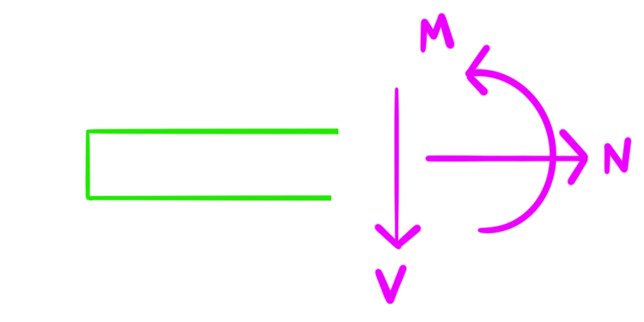
- Max moment, maximum or minimum moment occurs where shear is zero or changes sign, including at concentrated-load discontinuities. The custom solver places an integration station at every support and load boundary and integrates the shear curve between them, so a point-load peak lands on a station rather than between two.
Worked example
30 ft simple span carrying 0.9 kip/ft
Given
- Span L = 30 ft = 360 in, simply supported
- Uniform service-level load w = 0.9 kip/ft (the deflection step below treats it as such)
- W12×30, Ix = 238 in⁴, E = 29,000 ksi
Solve
R = wL/2 = 0.9 × 30 / 2 = 13.5 kipeach reactionV_max = 13.5 kip at each supportM_max = wL²/8 = 0.9 × 30² / 8 = 101.3 kip-ftat midspanW12×30, A992: F_y·Z_x/1.67 = 50 × 43.1 / 1.67 / 12 = 107.5 kip-ftif L_b ≤ L_p, this is the allowable flexural strength and it exceeds the 101.3 kip-ft demand. The simplified 0.66·F_y·S_x check gives 106.2 kip-ft. A complete AISC flexural check must also consider unbraced length, compactness, and lateral-torsional buckling.δ_max = 5wL⁴ / (384·E·I)the 0.9 kip/ft above is taken as a service-level load, so this is a serviceability check. In consistent inch units, w = 0.9 kip/ft = 0.075 kip/in= 5 × 0.075 × 360⁴ / (384 × 29,000 × 238) = 2.38 indownward, at midspanL/δ = 360 / 2.38 = 151For a W12×30 in A992, L_p ≈ 5.4 ft, and this example does not establish L_b. If the beam is braced so that L_b ≤ L_p the allowable moment is about 107.5 kip-ft against the 101.3 kip-ft demand; otherwise the applicable AISC lateral-torsional buckling provisions govern instead. Shear is checked separately. At service load the beam deflects to L/151. For scale, L/240 on this span would allow 1.50 in and L/360 would allow 1.00 in, but which limit applies is a project and code question, not one the calculator answers. Strength and serviceability are independent checks and either can govern.
Allowable stress design (ASD)
With max shear and moment known, the calculator runs a preliminary allowable stress check on the selected section.
M_allow = F_y·Z_x / Ω_b, Ω_b = 1.67compact section, L_b ≤ L_p (AISC 360-22 F2)0.66·F_y·S_xsimplified ASD yielding check; gives about the same answer for compact rolled shapesf_v = V / A_waverage shear stress on the shear areaF_v = 0.6·F_y·C_v / Ω_vΩ_v = 1.50 for a rolled I-shape with a compact web, else 1.67- Web area, not gross area, shear in a rolled shape is carried almost entirely by the web, so the check uses d·t_w rather than the gross area A, which understates the stress (on a W12x30 by a factor of 2.75). The applicable shear area and strength equation depend on the member type and shear direction; the calculator applies the appropriate AISC Chapter G provision for the selected section.
- Where 0.40·F_y comes from, for applicable rolled I-shapes with C_v = 1.0 and Ω_v = 1.50, the ASD allowable shear stress is 0.40·F_y. Other sections and slender webs use their applicable Chapter G provisions.
- Section modulus, use the applicable section modulus S_x for elastic bending stress. For unsymmetric sections such as tees and angles, the section modulus can differ by extreme fiber.
- Average, not peak, V / A_w is an average shear stress; actual shear stress varies across the section.
Deflection
Deflection is reported independently of strength checks when Ix is available. A beam can satisfy strength requirements and still exceed a project deflection limit.
- How it is solved, the moment diagram is integrated twice to obtain slope and deflection for the combined loading, including self-weight when applicable. Support boundary conditions are applied at the actual supports: v = 0 at simple supports and v = 0, dv/dx = 0 at a cantilever's fixed end.
- Maximum deflection, δmax is determined from the calculated deflected shape and may occur away from midspan or at an overhang tip. Combined loads are evaluated together rather than adding individual maximum deflections.
Standard cases
Cases the calculator solves
For checking a result by hand. L is the span or cantilever length, w is load per unit length, P a concentrated load, and a and b locate a point load (b = L − a). Use consistent inch units: L in inches, P in kips, w in kips/inch, I in in⁴ and E in ksi give δ in inches.
| Case | V_max | M_max | δ_max |
|---|---|---|---|
| Simple span, uniform load w | |||
 | wL / 2at each support | wL² / 8at midspan | 5·w·L⁴ / (384·E·I)at midspan |
| Simple span, point load P at centre | |||
 | P / 2at each support | P·L / 4at midspan | P·L³ / (48·E·I)at midspan |
| Simple span, point load P at a | |||
 | P·a / Lat the support nearer the load | P·a·b / Lunder the load | P·b·(L² − b²)^(3/2) / (9√3·L·E·I)at x = √((L² − b²)/3) from the support farther from the load, b being the shorter distance |
| Simple span, two equal loads P at a from each support | |||
 | Pat each support; V = 0 between the loads | P·aconstant between the loads | P·a·(3L² − 4a²) / (24·E·I)at midspan |
| Simple span, triangular load 0 → w₀ | |||
 | w₀L / 3at the loaded end; w₀L/6 at the unloaded end | 0.0642·w₀L²at x = 0.5774·L from the unloaded end | 0.006522·w₀·L⁴ / (E·I)at x ≈ 0.5193·L from the unloaded end |
| Cantilever, uniform load w | |||
 | wLat the fixed end | w·L² / 2at the fixed end | w·L⁴ / (8·E·I)at the free end |
| Cantilever, point load P at free end | |||
 | Pconstant along the beam | P·Lat the fixed end | P·L³ / (3·E·I)at the free end |
| Cantilever, point load P at a from the fixed end | |||
 | Pbetween the fixed end and the load; zero beyond | P·aat the fixed end | P·a²·(3L − a) / (6·E·I)at the free end |
Every case in this table is covered by an automated check that runs it through the calculator, on V_max and M_max as well as δ_max and its location.
Field notes
- A transverse load through the shear center does not introduce load-eccentricity torsion. Loads eccentric to the shear center introduce torsion not shown by the V/M diagram.
- Use the diagrams to inform splice and reinforcement locations, but consider shear, axial force, connection requirements, and constructability as well as moment.
- Flexure or serviceability often governs conventional rolled beams, but shear can control for short spans, heavy loads near supports, copes, and web penetrations.
- Web crippling, web local yielding and block shear at the connection are separate limit states and are not covered.
- Passing bending and shear does not mean the beam is serviceable. Check the deflection based on your project limits before settling on a section.
Educational reference only. Verify every result independently and apply the safety factors and load combinations required by the governing code and a qualified engineer.
Quick reference
- QR01 - Sling Tension
PDF · 579 KB — Static Pick Analysis - Sling Tension and Angle 2 vs. 4-Sling Comparison, Equations, Worked Examples, Field Notes + More
- QR03 - Beam Analysis
PDF · 651 KB — Static Beam Analysis - Shear, Moment, Deflection, Equations, Worked Example, Field Notes, Reference Table, + More
- QR06 - Steel Shapes
PDF · 264 KB — Steel Shapes - Shape Designations, Equations, Worked Examples, Field Notes + More
Related tools
- Steel Shape Properties Table
get Ix, Sx and Zx for the section you are checking the moment and deflection against
- Steel Weight Calculator
total the tonnage for the beam and its framing
- Fillet Weld Strength Calculator
size the connection for the end reaction you just found
Related reference
- AISC Shape Reference
every published series, by family
- W-Shapes
the family most spans are framed in
- W12x30: Ix, Sx and Zx
- The Full W12 Series
- ASTM A992 Yield and Tensile Strength