
Sling Tension & Sling Angle Calculator
Tool NotesWhat it does, the formula, and what it assumes
What this tool does
Works out what each sling leg actually carries on a symmetric two or four-point pick. Give it the load weight, the pick point spacing and the sling length, and it returns the sling angle and the tension in every leg.
It then sizes the hardware: the smallest wire rope, synthetic sling, roundsling or chain that carries that tension, and the shackle to go with it.
Formula
The load shares equally between legs because the picks are symmetric about the center of gravity. Each leg then divides its share by the sine of the sling angle, and that leg tension resolves onto the three axes at the pick point.
T = (W / N) / sin αtension per leg, N legs, α from horizontal; W and T in lbLoad factor = 1 / sin αwhat the angle costs youFx = T · (x/2) / LX Axis Force, along the member, lbFy = T · (y/2) / LY Axis Force, across the member, lb; 0 on a 2-sling pickFz = T · sin α = W / NZ Axis Force, vertical, lbT = √(Fx² + Fy² + Fz²)the components close back on the tension90° → 1.000 60° → 1.155 45° → 1.414 30° → 2.000the four worth memorizingAssumptions
The member hangs as a rigid body in static equilibrium. The crane hook sits directly above the center of gravity (CG), all slings are equal length, and the pick points are placed symmetrically about the CG so the load shares equally between legs.
- Symmetry, pick points are mirrored about the CG; with N legs each carries W/N of the vertical load.
- Hook over CG, the resultant sling force is vertical and passes through the CG, so the member hangs level.
- Static only, no dynamic amplification, shock, or safety factor is applied; these are the bare equilibrium values.
- CG location, taken at the geometric center of a prismatic member; an offset CG shifts the picks and unbalances the leg tensions.
Technical NotesDerivation, worked example, applications and checks
Variables
Every symbol this page uses, with the name it goes by on a rigging plan. Lengths are in feet, forces in pounds, angles in degrees. x, y and L are what you enter; everything else is solved from them.
W Load Weight, lbx Pick Spacing X, ft — along the membery Pick Spacing Y, ft — across the member (0 on a 2-sling pick)L Sling Length, ft — pick point to hookz Hook Height, ft — above the pick pointsr Horizontal Reach, ft — pick point to hook in planT Sling Tension, lb — per legφ Sling Angle X–Z — from the x-axisθ Sling Angle Y–Z — from the y-axisα Sling Angle X–Y — from the horizontal planeFx X Axis Force, lbFy Y Axis Force, lbFz Z Axis Force, lb — vertical- All three angles are measured FROM AN AXIS, φ off the x-axis, θ off the y-axis, α off the horizontal x–y plane — never from vertical. The lean off vertical is reported separately as 90° − α, and carries no Greek letter for exactly that reason.
Geometry & sling tension
The rigging is set by four dimensions, all in feet. x is the pick-point spacing along the member and y the spacing across it (y = 0 for a 2-sling pick), L is the length of each sling, and z is the resulting height of the hook above the pick points. Each sling spans a horizontal reach r from its pick point to the hook, so r, z and L form a right triangle, and the leg tension follows from the vertical force balance in the Formula block.
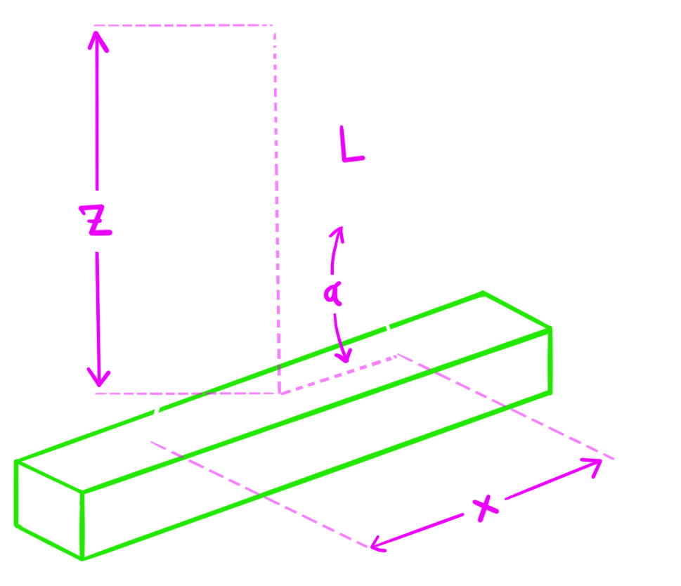
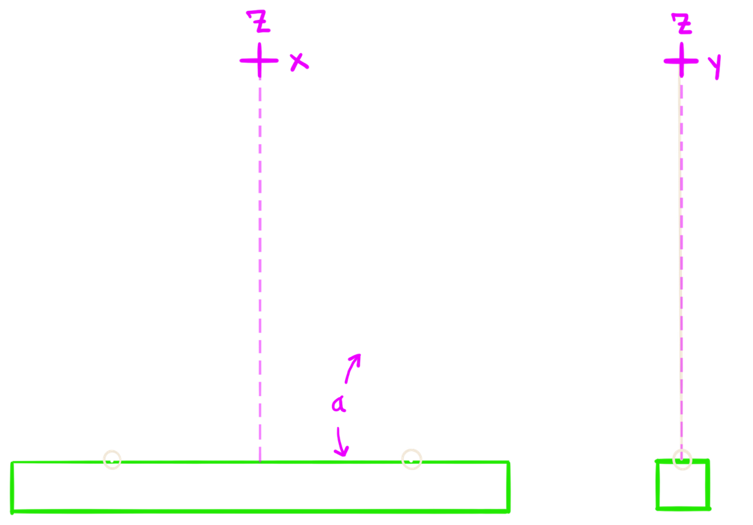
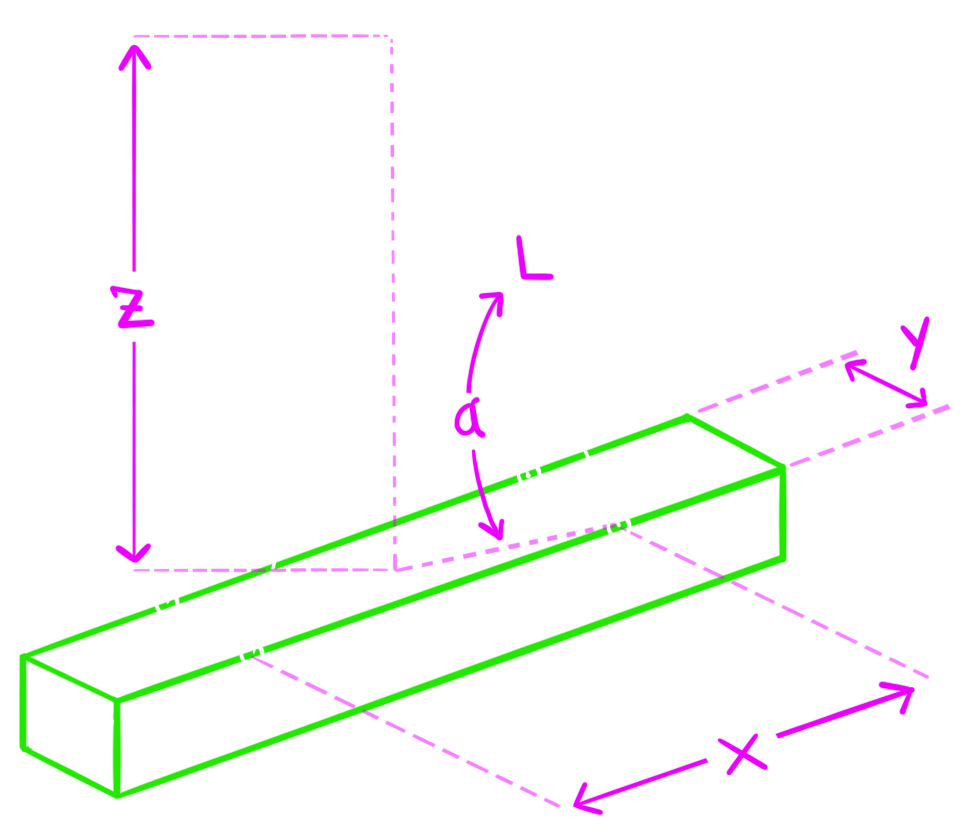
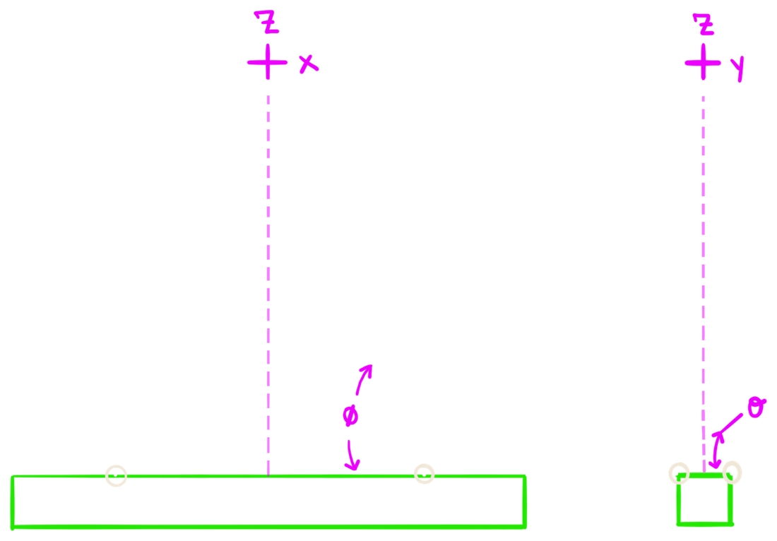
r = √((x/2)² + (y/2)²) horizontal reach, ft (y = 0 for 2 slings)z = √(L² − r²) hook height above picks, ftα = atan(z / r) sling angle, from the horizontal x–y planeφ = atan(z / (x/2)) x–z elevation, from the x-axisθ = atan(z / (y/2)) y–z elevation, from the y-axis (4 slings only)cot²α = cot²φ + cot²θ how the two elevations combine into α- L must exceed r, the slings have to reach past the plan offset before they can lift anything; if L ≤ r the geometry has no solution and the tool reports an error instead of a tension.
- Widening the picks costs height, for a fixed sling length, increasing x or y grows r, which shrinks z and flattens the sling angle, the usual reason a lift needs longer slings or more headroom.
- 2 slings collapses to one angle, with y = 0 the y–z lean disappears, r is just x/2, and φ and α become the same number. That is why the 2-point figures label only α.
Reading the sling angle
The tension formula uses α, the angle between the sling and the horizontal plane, because that is the angle the sling force actually makes with the vertical it has to resist. A rigger laying the pick out in the field usually reads the lean off vertical instead, which is simply 90° − α, and the tool reports that alongside it.
- α is the governing angle, not φ or θ, on a 4-sling pick, φ in the x–z view and θ in the y–z view are both steeper than α, because each shows only part of the sling's horizontal run. Sizing off either one understates the tension. The tool reports all three and uses α.
- The 30° floor is on α, ASME B30.9's practical minimum is measured from horizontal, so it applies to α. 45° in both elevations is only 35.3° of true sling angle, and 39° in both drops below the 30° floor.
- Squareness matters, the angles assume the hook is centered over the CG. If it is offset, the four legs pick up different angles and the load stops sharing evenly, no matter how symmetric the pick points are.
Resolving the leg tension
The tension acts along the sling, so it resolves at the pick point on the sling's own direction cosines: each component is T times that axis's share of the sling length L. Fx runs along the member and is the one that matters for the pick-point detail; Fy runs across it and is zero on a 2-sling pick; Fz is the vertical share and always comes back to W/N.
Fx = T · (x/2) / L X Axis Force, lbFy = T · (y/2) / L Y Axis Force, lb (0 for 2 slings)Fz = T · z / L = T · sin α = W / N Z Axis Force, lbT = √(Fx² + Fy² + Fz²) the three close back on the tension√(Fx² + Fy²) = T · cos α horizontal resultant, NOT the tension- Fx and Fy alone are not T, the two horizontal components resolve to T · cos α, the inward force at the pick. The tension is the hypotenuse of that resultant and the vertical Fz, which is why all three are reported. On a 2-sling pick Fy = 0 and T = √(Fx² + Fz²) in the x–z plane alone.
- Fz is the free check, it must equal W/N for every leg, whatever the geometry. If it does not, the spacing, the sling length or the weight was entered wrong.
- Flattening the angle grows Fx, Fz is fixed at W/N by the load, so everything a shallow angle adds to T shows up in the horizontal components. At 45° the horizontal resultant equals the vertical share; below that it exceeds it, and at the 30° floor it is 1.73 times the vertical.
Tension factor, 1 / sin α
What the sling angle costs in leg tension, before any dynamic allowance. The factor multiplies the vertical share W/N, so it applies per leg on a 2- and a 4-sling pick alike.
α = 90° (max — vertical) sin α = 1.000 factor 1.00α = 60° (rule of thumb) sin α = 0.866 factor 1.15α = 45° (increased tension) sin α = 0.707 factor 1.41α = 30° (high tension) sin α = 0.500 factor 2.00- At 30° on a 2-sling pick, each leg carries the whole load, the factor of 2.00 exactly cancels the halving, so a leg sees W, not W/2. The tool treats 30° as a floor and will not solve below it.
Worked example, 2-sling pick
A 10,000 lb beam on a 2-leg pick at 60°
Given
- Load W = 10,000 lb
- Two legs, symmetric about the CG
- Sling angle α = 60° from horizontal
Solve
Vertical share = 10,000 / 2 = 5,000 lb per legT = 5,000 / sin 60° = 5,000 / 0.866 = 5,774 lbAt 30° instead: T = 5,000 / 0.500 = 10,000 lbsame load, double the tension5,774 lb per leg at 60°. Drop the angle to 30° and each leg carries the entire load on its own.
Worked example, 4-sling pick
The same load on four legs, with the geometry solved from the spacings rather than assumed. Note how the two elevation angles both read steeper than the sling itself.
A 10,000 lb load on a 4-leg pick, y = 3 ft
Given
- Load Weight W = 10,000 lb
- Pick Spacing X x = 10 ft
- Pick Spacing Y y = 3 ft
- Sling Length L = 10 ft
- Symmetric about the CG
Solve
r = √(5² + 1.5²) = 5.22 fthorizontal reach, plan diagonalz = √(10² − 5.22²) = 8.53 fthook heighttan α = 8.53 / 5.22 → α = 58.5°φ = 59.6°, θ = 80.0°T = (10,000 / 4) / sin 58.5° = 2,931 lbFx = 2,931 × (5 / 10) = 1,466 lbFy = 2,931 × (1.5 / 10) = 440 lbFz = 2,931 × sin 58.5° = 2,500 lb= W/4, as it must be2,931 lb per leg. The check closes: √(1,466² + 440² + 2,500²) = 2,931 lb. The horizontal pair alone gives 1,531 lb, which is T·cos α — the inward force at the pick, not the tension. And α = 58.5° is flatter than either elevation reading, which is the trap a single view sets.
The member as a lift beam
Under its own weight the member bends between and outside the picks. The two pick points act as supports for a uniformly loaded beam with overhangs, so the steel sees hogging moment over the picks and sagging moment at midspan. Here L_m is the member length in feet; L stays the sling length from the Geometry & sling tension figures.
w = W / L_m self-weight, lb/ft (W in lb, L_m in ft)a = (L_m − x) / 2 overhang each end, ftM_pp = −w·a² / 2 moment over a pick, lb-ft (hogging)M_mid = w·L_m·(L_m − 4a) / 8 moment at midspan, lb-ftf_b = M / S_x bending stress; convert M to lb-in first, S_x in in³- Spacing trade-off, widening x lowers the midspan moment but raises the pick (overhang) moment; the two balance near x ≈ 0.586·L_m for a uniform member.
- S_x, not c / I_x, the two are the same identity only when c is the distance to the extreme fibre. On a tee or an angle the centroid sits near one face, so taking c as the centroid distance understates the stress (by more than 5× on some WT shapes). The tabulated S_x removes the ambiguity.
- Deflection, shown when the selected member carries an I_x, solved from the moment diagram at E = 29,000 ksi with v = 0 at the two picks. Self-weight only, so it is what the member does hanging in the slings, not what it does in place. The maximum can fall at midspan or at a free tip depending on the spacing, and the tips lift while the span between the picks sags. The Shear & Moment calculator covers the method, the assumptions and the standard cases in full.
Field notes
- Keep sling angles ≥ 60°, tension grows as 1/sin α, so a shallow angle spikes both the leg tension and the inward force Fx the member carries at the pick points.
- Hook over the CG, an offset hook skews the leg angles and the load sharing, however symmetric the pick points are.
- Do not assume equal load sharing on four legs, four-leg sharing is only equal if the load and the rigging system are sufficiently rigid and the assumption is justified. On a flexible load, or with unequal sling lengths, two legs can take everything — design the pick that way unless the load is genuinely rigid.
- Static values only, no dynamic amplification, shock or safety factor is included; fast picks and swinging push real tension higher.
- Then size the hardware, wire rope / sling SWL ≥ T and shackle SWL ≥ T, at a 1:5 SWL-to-MBF ratio. The ratio shall be verified by the manufacturer of the rigging elements, and their published rating governs — for wire rope and shackles alike.
- Longer slings, a longer sling raises the sling angle and lowers the leg tension, at the cost of headroom.
- Deflection is a separate check, passing bending and shear does not mean the beam is serviceable. Check the deflection based on your project limits before settling on a section.
Educational reference only. Verify every result independently and apply the safety factors and load combinations required by the governing code and a qualified engineer.
Quick reference
- QR01 - Sling Tension
PDF · 579 KB — Static Pick Analysis - Sling Tension and Angle 2 vs. 4-Sling Comparison, Equations, Worked Examples, Field Notes + More
- QR02 - Rigging
PDF · 1.0 MB — Wire Rope SWL - Selection, D/d Ratio, Sling Hitches, MBF Tables Equations, Worked Examples, Diagrams, Field Notes, Wire Rope and Shackle MBF Tables + More
- QR03 - Beam Analysis
PDF · 651 KB — Static Beam Analysis - Shear, Moment, Deflection, Equations, Worked Example, Field Notes, Reference Table, + More
Related tools
- Beam Shear, Moment and Deflection Diagram Calculator
full shear, moment and deflection treatment, including the standard cases and the deflection assumptions
- Wire Rope Safe Working Load (SWL) Chart
safe working loads for the rope diameter this pick calls for
- Steel Weight Calculator
establish the lift weight before you rig it
- Steel Shape Properties Table
weight per foot and dimensions for the member being picked